Monday, December 30, 2019

Translate - CAD data not languages

CAD Data Translation

A few years ago, I was involved with the introduction of a new product for viewing CAD files. It would view, measure, and perform some basic manufacturing type analysis of the models. Presenting this product to an aerospace manufacturer, the question came up whether the product was certified for certain data types. In other words, how would they know that once the file was translated and read in, that the data was exactly as was output?

If you were involved with 3D CAD data in the late 1980's and early 1990's, one of the biggest issues was exchanging data between different systems. For reading 3D models, back then IGES was a common exchange format, with SET and VDA less often used, at least in the U.S. 


Bezier, B-Spline, Degree, etc.

Back in the 1990's, CAD systems used different math for their 3D data. The most common were Bezier and B-spline. I don't want to get into deep math here, so if you're interested in that, I'll put some links at the end. 

Splines and freeform surfaces are basically polynomial math equations. Different CAD systems could accept splines up to a maximum degree, where degree is the largest exponent of the polynomial equation, and the order was typically the degree plus one. (if the equation went to the 5th exponent, it was a order 6 curve). Bezier systems typically allowed for polynomials of high order, some as high as 13.


Bezier patches
Bezier patches


B-Splines on the other hand use several lower-order polynomial equations and tie several of them together (with knots) to make more complicated curves, rather than just making one equation with higher exponents. NURBS, or Non-Uniform Rational B-Splines became the most popular data format for 3D freeform data. 


B-Spline patches
B-Spline Patches


So if you were reading data between a b-spline system vs a Bezier system, it had to rebuild the surfaces for their own database. Any time you rebuild data, there is always a tolerance involved, hence the question "how do you know it's exact?" 


Solid Models

Solid modelers are usually B-Rep or Boundary Representation.  That is they are defined by topology and geometry. Topology includes faces, edges, and vertices. Whereas geometry is surfaces, curves, and points, that make up the topology. Some faces can be defined by an elementary type, such as planes, cylinders, conics, spheres, etc. These can be translated more exactly, because a plane is a plane in most any system.


Today

These days, you don't hear much about the order of faces in translation. New translation formats have increased reliability, and accuracy is close enough for most manufacturing needs. So why all of this you ask?

Recently, I was contacted by someone interested in buying a small Tormach mill, and I was used as a local reference. They wanted to see first hand the finish the mill is capable of. I asked what they cut, and found a part on GrabCAD (credit to Winston Jennings for the design) that was representative of what they do. 


Original model from GrabCAD


I loaded the part into two CAD systems, and saw a significant difference on screen. In NX, the part on screen matched what was shown on GrabCAD.


Model in NX
Model in NX


However, when loaded into Fusion360, not only did colors not match up, the shading made it look like there could be a problem. Not only does the shading have wrong tesselations, it appears that the face in question has a trim boundary on it that the original does not.


Model in Fusion 360
Model in Fusion 360


After further examination, the surface data seemed good enough for manufacturing. The original file is Parasolid, which is the same geometry kernel that NX uses, and Fusion360 does not, meaning it had to translate or convert the data. We wonder if this translation caused some of the rendering tesselation issue.

This is one of the reasons it is often recommended to perform manufacturing in the same system, because how do you know the data is exact? Below is the part off of the mill.
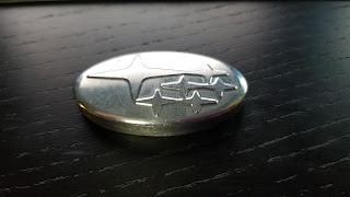

Milled part - from Tormach 440


Hence the original question from the aerospace company, "How do you know the data is exact?"


Links:

Want to know more about Bezier and B-splines? - Here are some links

https://www.cs.unm.edu/~angel/CS534/LECTURES/CS534_07.pdf
https://www.cs.bham.ac.uk/~slb/courses/Graphics/g95.html
https://pdfs.semanticscholar.org/4982/54fdd06e219cb2af519386a517fef887526f.pdf
http://www8.cs.umu.se/education/examina/Rapporter/461.pdf.pdf







Tuesday, June 18, 2019

Siemens PLM Realize Live 2019

Realize Live! 2019 at Cobo Hall

Siemens booth at RealizeLive

The show for Siemens PLM users and resellers, Realize Live! has recently ended. This year marks the first year Siemens put on the show instead of the community. Without a doubt, Realize Live! 2019 was a success. 

Some numbers at a glance:

  • Over 550 Sessions
  • Over 175 customer presentations
  • Over 125 partner booths
  • Around 50 hands-on training classes (including an awesome class on convergent models)
  • Twelve product breakout connections
  • Knowledge theaters
  • Daily Keynotes
  • Daily professional development
  • Networking events each evening


On top of all of that, on June 10th was the ASME Additive Manufacturing Forum. With industry experts covering a variety of topics at each session. 

Edited to add - visit the official blog post on the Siemens PLM forum


Keynotes:


Some of the Keynote speakers included:

  • Tony Hemmelgarn - President and CEO of Siemens PLM.
  • Kelly McDonald - top expert on marketing, customer service, and customer trends.
  • Seth Mattison - Internationally renowned expert and author on workforce trends, generational dynamics, and business strategy.
  • Peter Sheahan - the founder of Karrakins Group, knows as an innovative business thought leader.

Some points from the Keynotes:

Tony Hemmelgarn mentioned while subscriptions and cloud are available, people will not be forced to go to them. 
Additive Manufacturing is more than just designing and printing. It's an end to end solution bringing all the pieces together; design, simulation; analysis, printing, post-processing, scheduling, resources, etc
Tony mentioned part of the strategy is making a product that fits the people, and not putting them into a persona.

Peter Sheahan gave a pretty good speech. Turns out his employees liked his company but didn't like him, in large part on how he conversed. He made conscious changes and improved his rating with his employees.
Peter also talked about staying relevant, and constant learning. He said:

  • If your company is not learning as fast as the outside world, you are becoming irrelevant.
  • If your team is not learning as fast as the outside world, you are becoming irrelevant.
  • If you are not learning as fast as the outside world, you are becoming irrelevant.

ASME Additive Conference

The one day ASME Additive Manufacturing track included sessions on:

  • Disruptive Product Design and Distributed Networks
  • Building a Business around Additive Manufacturing
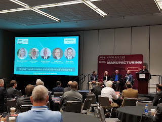
  • Digital Transformation and Additive Manufacturing
  • The Challenges and Opportunities of AM Production
  • AM Materials Advances and Impacts


There were other Additive breakouts during the rest of the week such as

  • Introduction to Multi-Axis Additive Manufacturing
  • Best of Both Worlds: Combining Additive and Subtractive
  • Designing for Additive Manufacturing

Exhibition Hall

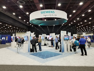
Many companies had booths in the exhibition hall, so attendees could stop by to learn more about their products or services. The Siemens booth had over a dozen kiosks showing various solutions that solve some of the toughest design, engineering, and manufacturing problems. 

Well done event

Realize Live! 2019 was a well organized and professional event. Many users got to meet product managers to discuss their particular needs, and plans for moving forward. 

While some companies don't like to pay to send employees to events such as this, it is the one time a person has access to some of the best resellers, applications engineers, product managers and others all at one time. It's highly recommended for next year.

Detroit's Cobo Hall promoting what's happening inside

Companies that use Parasolids
Companies that use Parasolid, in one way or another

There was a cloud theme to the event


Peter Sheahan at the keynote

Digital Transformation and Additive Manufacturing
Digital Transformation and Additive Manufacturing 

Advances in Additive Manufacturing Materials

Disruptive Product Design and Distributed Networks

Cloud Solutions Theme
Cloud SolutionsTheme

They made t-shirts live

One of the kiosks at the Siemens booth

Universities that use NX were in attendance
Universities that use NX were in attendance 


Sunday, June 2, 2019

It's not just a job, it's a wardrobe

It's not just a Job, It's a Wardrobe

One year absence

If you are one of the three people subscribed to this blog, then you may have (though I doubt it) noticed there have not been any new posts in a while. 

There's a reason for that. 


Changed Jobs


If you read this blog in the past, first I'd like to thank you. You may remember I worked on the CAM side of things with Autodesk. Well, that's not the case anymore. My position was one of the 1,100+ that in late November 2017, Autodesk announced would be cut. Kind of a Happy Thanksgiving and Merry Christmas announcement. 

I was very fortunate to be able to find a new position at Siemens PLM, working on the team doing Additive Manufacturing software, and started in March of 2018. I have not posted new blogs because I've been learning NX, and, frankly have been very busy.

The last year and a half took me to Rapid, IMTS 2018, Materialise Expo, business trips to Denver, California, and several locations in Germany. I've taken training for Scaled Agile Framework (SAFe) development methods. It's been challenging, rewarding, and fun. I can safely say we have one of the best teams possible. 


The Wardrobe

I've been involved in the CAD industry since 1990, many of those years working directly for the software developers. Often in an Applications Engineer or similar technical role. This required travel to customers and trade shows. Going to shows means getting company shirts. Hence, we would often make a joke that it's not just a job, it's a wardrobe. My closet has been full of shirts from previous employers. When one company was purchased by another, it became an opportunity for a new wardrobe. 

In fact, that last stint with Autodesk was not my first. I actually worked for Autodesk back in the early 1990's from their acquisition of Micro Engineering Solutions. When switching jobs, I usually throw out the shirts, to make room for more, but kept this one, because I thought it was very cool.


Solutions 3000 was the product of MES, and was somewhat unique in that you would pick first, then issue the command. The NURBS surfacing first became AutoSurf, then eventually the NURBS surfacing of Mechanical Desktop. (All products are part of the graveyard I believe)

After purchasing Micro Engineering Solutions, Autodesk purchased Woodbourne, which was the parametric solid modeling for AutoCAD, and the solid modeling portion of Mechanical Desktop, and I believe most of that team was involved in the creation of Inventor.

However, Solutions 3000 was not just a CAD product, but also included CAM functionality. At the time, Autodesk did not want to be in the CAM market, and actually let Camax (makers of Camand) resell it. Camax was eventually purchased by SDRC, which as a competitor to Autodesk ended up allowing the contract to resell Solutions 3000 be canceled. SDRC was of course eventually purchased by Unigraphics, which was eventually purchased by Siemens. 


CAM Software

For the longest time, Autodesk shied away from CAM software and manufacturing.  Certainly, CAM  sales are only a small percentage of CAD sales. There were many who said no one at Autodesk actually knew about manufacturing, as they have never had, "a chip stuck in their shoe." 

Autodesk's reluctance to compete in the manufacturing field changed sometime after Carl Bass became CEO of Autodesk. The company acquired manufacturing products like HSMWorks, Delcam (PowerMill), NetFabb (3D Printing software), TruNest (nesting and fabrication software), and probably a few others. Including some really good people with a solid manufacturing background.   

This is why I was recruited to work at Autodesk back in 2015, because they were making a bigger push into manufacturing.

Which leads me to my latest group of shirts I need to clear out. I've been waiting, but now need the closet space. 


One thing that is interesting is the branding, bundling, and product names during that short time. As evidenced by the various shirts. There was Autodesk CAM, which wasn't the name of an actual product, but rather what they were working on. People didn't like that name, and some new internal marketing was called "Autodesk Advanced Manufacturing". That name was liked less. 

HSMWorks was the name of the SolidWorks version, and Inventor HSM was the name of the version for Inventor, and they were sold separately. This is the same CAM software inside Fusion by the way. Next, a bundle named Autodesk HSM came out, where you got both the SolidWorks and Inventor versions. At some point, that stopped being a separate product, and you had to buy the Product Design and Manufacturing bundle to get CAM. 

Since then, Inventor HSM has been renamed Inventor CAM which is not to be confused with InventorCAM by iMachining. Yes, I guess that space makes a difference.

With so many changes in branding, naming, bundling in such a short time one might still wonder if Autodesk really knows what they want to do with manufacturing. 


Happy for the Opportunity

It may sound like I'm dumping on Autodesk, but that's not the case. I enjoyed working there, learned a lot, and they were a good company to work for. The people were pretty much great and helpful. During the reorg of 2017/2018 I was surprised to learn popular, long term employees, like Lynn Allen, were also reorg'd out. Her classes at Autodesk University were the largest, always packed, and had standing room only. 

My team had some great times, like when we brewed and gave away beer with a manufacturing theme. I was saddened to hear some other people I know from the mfg side have been cut since, or left for new opportunities.


Additive Manufacturing

With all that said, Siemens is doing some really kick-butt things with Additive Manufacturing. Both flatbed and multi-axis. You can find out more at Realize Live (the Siemens PLM customer event) or the one day track on Additive Manufacturing.

Now, I have to find out where my shirt for the event is....


Realize Live, The NX event comes to Detroit

Realize Live! The NX event comes to Detroit

Realize Live

Consider attending Siemens PLM Realize LIve event, June 10-13 at Cobo Center, Detroit.
This is the premier industry solutions event, connecting the Siemens Digital Industries Software community with peers, partners, and products while promoting networking opportunities to learn, grow, and optimize your toolset.

Yes I mostly copied that from the Realize Live event page


Additive Manufacturing

Can't make it to the whole Realize LIve event, but interested in Additive Manufacturing? There is a one day track focusing just on Additive Manufacturing. 

Speakers for this day include: 
Joe Veranese, America Makes Greg Hayes, EOS Ellen Lee, Ford Motor Company Brian Neff, Sintavia Greg Morris, Consultant Todd Grimm, TA Grimm & Associates Bryan Crutchfield, Materialise Scott Crump, Stratasys Dr. Michael Grieves, Florida Tech Kevin Quinn, General Motors Michelle Bockman, HP Marcus Seibold, Siemens Gas & Power Steve Chillscyzn, Evolve Annie Wang, Senvol Aaron Frankel, Siemens Digital Industries Software Kevin Creehan, Arconic Doug Ramsey, Hackrod Slade Gardner, Big Metal Additive

Plus I'll be there at many of the sessions. I'm also delivering two presentations during Realize Live (though on days other than the one day AM track) 

Best of Two Worlds: Uniting Additive and CNC Manufacturing  (June 13th, 2:45)
and
Multi-axis additive manufacturing with NX  (June 12, 2:45)


Check it out, and if you end up visiting, let me know and we can meet up.

Monday, January 22, 2018

Surface Finish on Contoured Parts - Part 2

Milling the Fusion 360 Reciprocating Saw Demo

In part one of our blog on milled surface finishes, we looked at some generic information regarding surface finishes. In this particular blog, we will look at the steps used to mill a scaled-down version of the Autodesk Fusion 360 reciprocating saw demonstration and training part.

Note that this is just one of several methods that can be used to mill the part. Other people will have their own preferences with their own logic behind those preferences. Feel free to share your own tricks and experiences in the comments section.


Inspiration

The inspiration for this is the same part, milled full scale, by Titans of CNC to be used as a display piece by Autodesk at tradeshows. Titan's piece is fantastic, with a really good finish, but it also weighs about 60 pounds and is fairly difficult and expensive to ship to all the shows. (See Titan's YouTube video here)

Our goal was to mill a smaller version that could be used as a simpler and smaller showpiece. This was going to be milled on a Tormach PCNC 440, and was scaled down by half to fit into the work envelope of the PCNC 440. The question was whether we would be able to achieve a comparable surface finish to the Haas VF6 SS used by Titan.

Below is an image of Titan's part


Roughing

We utilized an Imco 3-Flute Streaker for the roughing. First a 1/2" diameter cutter (.52 DOC, .05WOC) to remove the bulk of the material, and a 1/4" diameter (.26 DOC, .04 WOC) for re-roughing or rest material roughing. 

Here is a slideshow, showing the roughing and re-roughing operations. Full video was difficult as coolant and chips obscured the video capture. 

When the 1/2" tool was finished it looked like the picture below. There is extra material leftover inside the pocket for the grip/handle, which needs to be removed by a smaller tool. Also, the stair steps are fairly large for the semi-finishing tools to be used, so it was our goal to smooth those out a little as well.

One can automatically re-rough the leftover material from previous operations. 
If you use a second adaptive clearing operation, depending on your parameters and tolerances, you may get some undesired air movements. John Saunders from NYCCNC did a really good video on removing the "whisper cuts", but those tactics do not always work on 3D contoured parts, plus we did want to knock down the stair steps a little.

Alternatively, you run the adaptive clearing just inside the pocket, so that the full material there is cleared away, then run some other cutterpath everywhere else. In this case, a contour cut. The two cutterpaths together allow for a smoothing of the rough model.
The roughed out part, from the 1/2" and 1/4 inch is shown below.

Semi-Finish and Finish

Although there are many different finishing strategies which can be used, we chose to use a combination of a parallel cutterpath (planar finishing), along with the contour cutterpath (Z-Level finishing) utilizing a slope option. For more information on the differences in strategies, and what the benefits of this are, see Part One of the blog.

This strategy was used for both the finish and semi-finish. Only the stock allowance and stepovers would differ. With Semi-finishing we left 0.005" of material for a finish cut with a .020 stepover. With finishing, we cut to net zero, with a 0.005" stepover. The two cutterpaths work together to cove the part completely, without large cusps or scallops remaining. 
After the semi-finish operation the part looked like below:

And during the actual finish process with the 3/8" ball


We used a 3/8" ball mill for most of the finishing, as it would deflect less than a 1/4 inch, and all of the radii of the part would still be milled. We used a 3/8" bull nose with a 0.015" corner radius for the bottom of the part to get a relatively sharp corner, yet still achieve a smooth finish.

Want to watch the semi-finish operation, check it out below. Sped up to save time.


Tips

During roughing operations, we had to pause four times to remove chips. Even so, many of the images during roughing show a lot of chips in the mill.

During finishing, we would check the runout in the tool and holder prior to milling. Using R20 collets, it is easy to have excessive runout if tightened too tight or put together incorrectly. We would check the runout and adjust the tool and holder until we could minimize runout, though we were never able to get it to zero. 

Polish

We can say the part is not hand-polished, but it is polished, so we can share another tip on surface finish. I have a friend that made small molds for the badges placed on cars. He would set several up on his mill at one time, program all of the parts, hit cycle start and practice some golf. Afterwards, he would place a small polishing bit in, with some compound, program that, let the machine run while practicing more golf.

In this case, you can use Dremel polishing bits with a 1/8" shaft. Simply place some polishing compound on your part, and use the polishing bit in your mill with a 3D cutterpath like Scallop. Let it go while you practice a round of golf, or do other work around the shop. For this part, we used the large cylindrical bit, approximately 0.42" in diameter and a spindle speed of 9000 RPM.


Conclusion

Milling 3D contoured parts is quite different from milling prismatic parts. Excellent surface finishes are possible, with almost all mills, with careful programming and strategies.


Friday, January 19, 2018

Surface Finish on Contoured Parts - Part 1

Surface Finish on 3D Contoured Parts

This blog is derived from a previous class at Autodesk University based on Surface Finish and can be found at this link

Special thanks to Imco Tools for providing the cutters for this experiment. Also to Tormach and their PCNC 440, where all the testing was completed. All cutterpaths were made in Autodesk Fusion 360

Surface finish is defined by:
  • Roughness - finely spaced surface irregularities. In engineering, this is usually meant by surface finish.
  • Waviness - measures of surface irregularities larger than roughness; usually from deflection, warping, or vibrations.
  • Measurement - Actual measurement of finish, either via contact or non-contact methods.
When dealing with 3D contoured parts, and parts used in moldmaking, casting, patterns, etc. we often use a "street" definition of surface finish, how much time will be spent polishing parts. As all CNC milled parts will have some form of tooling marks left on them.

When examining surface finish, you may often use some form of visual tool, such as the template shown below.

There are many factors that work together for your final surface finish, and some of those are:
  • Tolerances in CAM system
  • Toolpath styles
  • Stepovers
  • Tool types and holders used
  • Machine controllers and their capabilities
  • Rigidity and accuracy of the milling machine
This blog is going to focus on the CAM system; tolerances, stepovers, and toolpath styles.

This blog will use a relatively simple 3D Contoured part, which is actually a cover for a jack connection for a Fender guitar. If you would like the file to practice with yourself, you can download the STEP file


Tolerance or Chordal Deviation

When dealing with 3D contoured, you are dealing with faces. The cutterpaths created by the CAM system on the faces will be through many small straight line segments. These will be represented on your CNC mill as hundreds, and sometimes up to millions, of G01 point to point movements on your CNC machine. 

The chordal deviation is shown in the image below. The tighter the tolerance used, the more points that will be created during the CAM calculation.


On our part, you can clearly see the difference in the picture below. The only difference in the two parts is the one on the left was milled with a very loose tolerance of 0.12mm (.0047") and the one on the right used a tolerance of 0.01mm (.0004"). 


Stepover and Cusp heights

When finish milling 3D contour parts, ball nose or radius nose cutters are often used. When used, there will be scallops or cusps leftover from the are between the stepovers in the CAM cutterpaths. This scallop, plus a calculation are shown in the image below (R is tool radius, Cusp is desired cusp height, R-Cusp is used in the calculation)

Unfortunately, the scallop height calculation is only constant if the face is horizontal. When you have 3D contoured shapes and changing slopes, the scallop left behind actually changes, and often increases, as shown below, where the scallop on the right is actually higher than the one on the left, for the same stepover.

You can really see this come into play on the images below. Where the image on the left used a 0.8mm (0.031") stepover and the part on the right has a 0.254mm (.010") stepover. The difference in the roughness and cusp height is very noticeable


Cutterpath Styles

Good surface finishes for 3D contoured parts generally require tight tolerances and smaller stepovers. Also, the milling strategy can have a great affect on the finished part. 

Common cutterpaths for finishing include a parallel planes strategy (sometimes called parallel or planar), some type of top to bottom strategy (usually called z-level finishing, or contour or water level finishing), and a constant scallop options (sometimes called equidistant or 3D scallop finishing). 

Other strategies like morph and spiral are also available and may be covered in future articles. 

They all have their advantages and disadvantages, and you choose the strategy based on the needs and part geometry.

Parallel or Planar

This cutterpath strategy uses slices in the X, Y or some angle in between. 

Fast to calculate, this can leave larger cusps when steeper surfaces are more or less parallel to the cut direction as shown in the images below. The left is a parallel cut in the "Y" direction, and the arrow shows where the cusp may be undesirably high. On the right is the cut in the "X" direction, which has the same issue, just in a different location.


Z-Level Finish (or contour, or water level finishing)

Utilizing a Z_Level finish is very popular in moldmaking, especially with hard materials. The tool starts at the top and works it's way down, rather than going back and forth and "bumping" into walls and features. However, depending on the geometry shape, you still can have large cusps let behind as shown below.


3D Scallop (or equidistant)

Unlike the other two cutterpaths, this one does not utilize cutting by planes. The stepover is calculated in a 3D fashion, and the toolpath will keep making collapsing movements. This type of cutterpath will leave the same scallop or cusp everywhere, and usually have fewer retract movements in the process, all advantages.

One disadvantage of this type of cutterpath are tool deflections and vibrations are in different directions all the time, as the tool is sometimes going uphill than downhill than around, etc. Also, the collapsing corners can often leave finish marks on the part, sometimes affectionately referred to as "snail tracks". Shown in the images below.


Slope Based Machining

Planar cutterpaths work great on relatively shallow parts, and Z-Level cutterpaths work well on relatively steep parts. If you use the best of both of those on parts that have both shallow and steep parts, than you can get a great surface finish, and improved tool dynamics.

That is the concept of slope based machining. If 0 degrees is horizontal, and 90 degrees is vertical, then you can limit cutterpaths to certain sloped areas. The image on the left uses a parallel strategy, but only for an angle of 0 to 45 degrees. The image on the right uses a Z-Level strategy, for an angle of 40 to 90 degrees, allowing for some overlap. This completely finishes the part, and leaves no large scallops or cusps to be concerned with.

For the finished part using the combined strategy and slope angles see below:

Pencil Trace

Lastly as a tip, we would generally recommend running a Pencil Trace operation prior to your finishing operation. This will pre-relieve the extra material int he corners, allowing for a smoother finishing experience.

A pencil trace is where you run a tool in the corners of the part, at least the areas where the corner radius is about the same or smaller than the tool in question, shown below.


The difference in your finished part is fewer tool vibrations or getting "pulled in" the corners when finishing. In the image below, the part on the left did not use a pencil trace before finishing, and the part on the right did. Note the marks in the corners. Even though it was a parallel finish, the marks are normal to the surfaces, showing the tool deflected at those locations.


Conclusion

Use a tight tolerance and tight stepover for fine finishes, and match the cutterpath to your part, or use slope angles if appropriate.

Part 2

In the second part of this blog entry, we will look at how we milled the Autodesk Fusion 360 sample part, the reciprocating saw mold, on a Tormach PCNC 440, and got the desired finish as shown below.